Entities
The native entity types available in DigFindR are as follows:
LINE
As seen above a line is shown in the selected state on the right. A line entity has two handles and a central grip handle that can be used to move the line. Either handle at the ends of the line can be moved independently, changing the length and angle of the line.
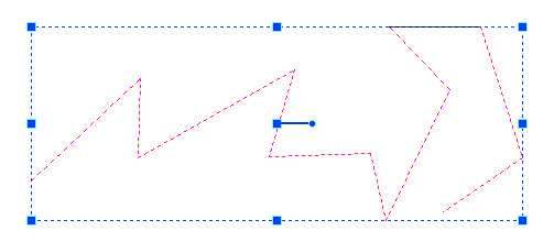
Lines can be drawing in serial mode as well. A serial line is shown below in the selected state. Note the bounding rectangle with grips at the corners and a rotator in the center. A serial line is composed of separate lines, any of which can be selected individually. Serial lines share common end points (handles).
CIRCLE

A circle is defined by a central point with all points on the circumference being the same distance from that central point. In the selected state as seen on the right, there are four grips and a central handle that can be used to move the circle. There is no rotator for a circle and the four grips on the circumference can be used to resize the diameter of the circle.
ARC
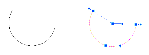
An arc is a more complex entity which, in the selected state seen on the right, has a special triangular grip used to resize it, while it also has two dot-like handles that can be used to adjust the arc-length. There is also a rotator handle in the center of the arc, and a grip handle on the arc circumference used to move the arc.
ELLIPSE

An ellipse is a closed line basically composed of two arcs mirroring one another. As an entity in the selected state, seen above on the right, the ellipse has four handles, a rotator, and like the arc, the ellipse has two dot-like handles that can be used to excise portions of the orbit line. To resize the ellipse, grab one of the handles with the mouse cursor and move in any direction.
RECTANGLE
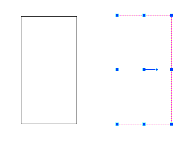
The rectangle is a four sided figure having 90 degree angles at each corner. In the selected state, seen above on the right, the rectangle has eight handles and a rotator in the center. The handles found midway through the sides can be used to stretch the rectangle, while the handles at the corners can be used to scale the rectangle.
POLYLINE
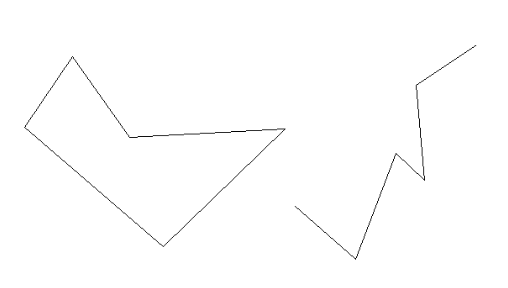
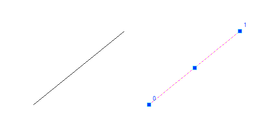
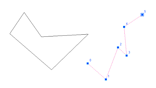
A polyline is an entity composed of line segments in series, similar to a serial line entity, however, the line segments combined make up a single entity, and in the selected state as seen below, the points where the segments attach to one another are called vertices (vertex is singular).
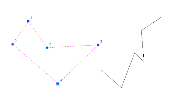
The polyline on the left has five vertices, 0 through 4, and because the polyline forms a closed figure, it is by definition a polygon. The polyline on the right has five segments as well, but it does not form a closed figure. When selected the polyline on the right has six vertices, 0 through 5. Any vertex can be selected by the mouse cursor and move independently of the other vertices, changing the overall structure of the polyline.
Polylines exhibit features that can be changed via the Properties Window, such as rounding the vertices, illustrated below.
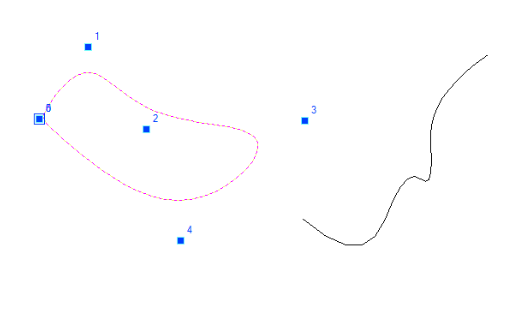
Polylines can also be morphed throughout their extents into several types of splines (smoothed polylines) via the Property Window, as seen below.
POLYGON
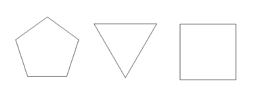
DigFindR has an additional entity type that can be constructed directly as a polygon having sides of equal length. These are actually nothing more than closed polylines, however, for convenience, a LiteCAD dialog is activated giving you the choice of the number of sides the polygon will have, and the entity will be constructed by use of a circle. For example as seen above, a pentagon, a triangle and a square are easily laid out with sides of exact equal length. While a square is a rectangle, using this tool will guarantee that the resulting rectangle is a true square, something that might be more difficult to build using serial lines or polyline entity(s).
TEXT
To place text into the Map Window a LiteCAD dialog will appear which you use to input the text string and set other parameters as desired. Normally, it is most convenient to place the text in the Map Window dynamically, size it, and rotate it as desired. The dialog looks like this:

In this default configuration of the dialog, the options for manual insertion, sizing, and rotation are checked. The style will be the drawing's default style, with a width factor of 1 and an insertion point of bottom-left. Once the text is set in the Map Window, the text string can be selected and these parameters can be changed as desired. The text contents would appear as seen below in a selected state. Note the handles which can be used to size the text string in height and width, as well as overall (use the corner handles). There is also a rotator at the insertion point, lower left.
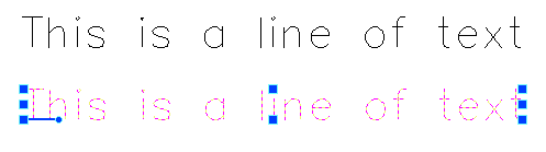
In this example, the text is "Standard" style, which for all new drawings in DigFindR is set in the Simplex font. Simplex is a stroke style especially designed for plotters.
MULTI-LINE TEXT
Unlike a regular single line of text, a text string laid out in more than one line must use a delimiter to separate the lines. Rather than using an Enter keystroke to start a new line, you place your text into a text box and use a special delimiter character to produce a new line. This special delimiter is the "\P" string (a backslash and a capital P character). Before building your multi-line text string, you will be required to set out a bounding box in the Map Window where the text will be set, then the text box will appear as seen below:
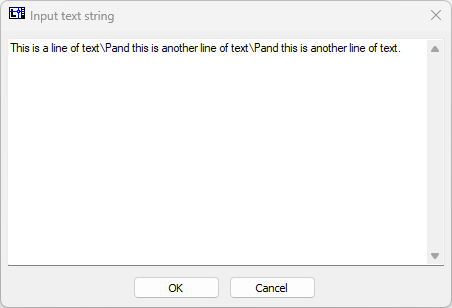
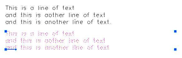
Click on the OK button and the text will appear in the Map Window as seen rendered below and as it appears in a selected state. Unlike a single text string, you can not stretch the text in height and width. The selected multi-line text string can be scaled from each corner handle, and rotated using the rotator in the lower left corner. Using the Properties Window you can modify the text otherwise. In this example there is a mis-spelling in the second line. To correct it, select the text and click in the Properties Window on the Contents line to summon the Input box, where you can make modifications as desired.
Be aware that you can not paste text into the Input box that contains embedded carriage return characters. This will cause DigFindR to crash.
.
HATCH
Hatching is an entity type used to add patterns to polygons, typically found on maps or other illustrations requiring zone delineation. To add hatching to the Map Window, you select a polygon (a closed polyline), then select the Hatch menu choice from the DRAW MENU. The LiteCAD Hatch dialog will appear, giving you the choice of your desired hatch pattern as shown below:
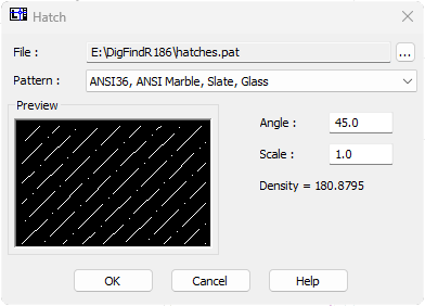
Once you have chosen your hatch pattern, the selected polygon will fill automatically with the chosen pattern. Be aware that the hatch might not appear as it did in the LiteCAD Hatch dialog. This is caused by the scale of the hatch pattern as applied to the polygon. To change the scale, select the hatch and change its scale in the Properties Window.
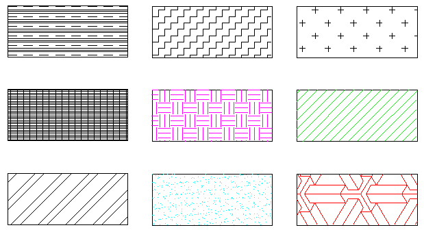
Hatch can be modified with scale, color and angle. The available hatch patterns are contained in a file found in the DigFindR home directory called "hatches.pat" which is distributed with the original installation. Some samples of hatching are shown below:
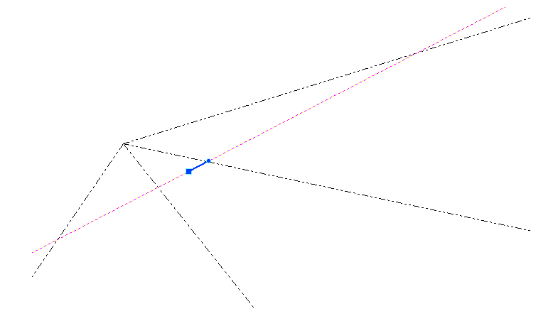
CONSTRUCTION LINES
Construction line entities are generally used to setup boundaries within the Map Window. There are two types; the ray, and the infinite. The ray has a single end point, while the infinite construction line has no end point at all. Construction lines are easily located in the Map Window because they always extend beyond the borders of the drawing/map. You only need to zoom to the extents of the drawing to find them. A single infinite construction line is shown in the selected state below, along with several rays.
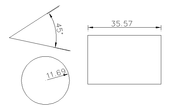
DIMENSIONS
While you probably will not make use of them often, if at all, you can add LiteCAD dimensions into your drawings as desired. Dimension text is fixed in size and can only be altered via the Property Window. Seen below are angular, radial and linear dimensions of an angle, a circle, and a rectangle.
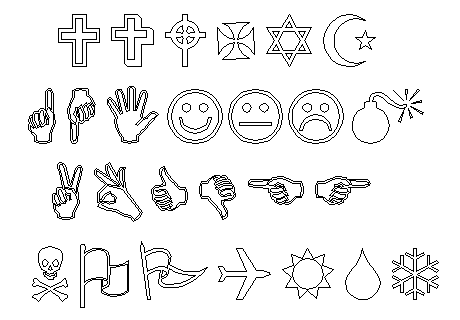
SYMBOLS
Everything drawn in the Map Window is an entity of one type or another, including text. In the standard Windows operating system, a number of fonts are included with the system and a few of them contain symbols rather than text characters. These are the Wingding and Webding fonts. You might have others installed on your own system such as the ESRI fonts for example that contain mapping symbols. To add these symbols to your drawing, you type from the keyboard and use the symbol font. Once these 'characters' are added to the Map Window, they may be edited as single or collected groups. Seen below are some of the Wingding Regular font characters as drawn in the Map Window, and then exploded.
RASTER GRAPHICS
Strictly speaking, raster graphics are not CAD entities in any real definition of the word, however they have become instrumental in map design and production since the advent of digital media. In digital form, aerial photos can be used in maps as defining layers and have become almost essential to map-making as we know it. Therefore, their use in DigFindR is also considered essential with tools that make use of them.
Raster graphics are images made from pixels, with those pixels having rectangular form, and portrayed by the computer through its screen or printer. The computer screen is composed of pixels displayed in a raster, or an X and Y grid structure if you like. There are many types of raster graphics, however the ones most common are the JPG, TIF, BMP and PNG types. The higher the density of the pixels, the more appreciable the quality of the image to the human eye. The higher the density the larger the file size in bytes, and the larger the file size, the longer it might take to load the image and move it around in the CAD's memory. The purpose of the map will generally dictate the density of the images used in it.
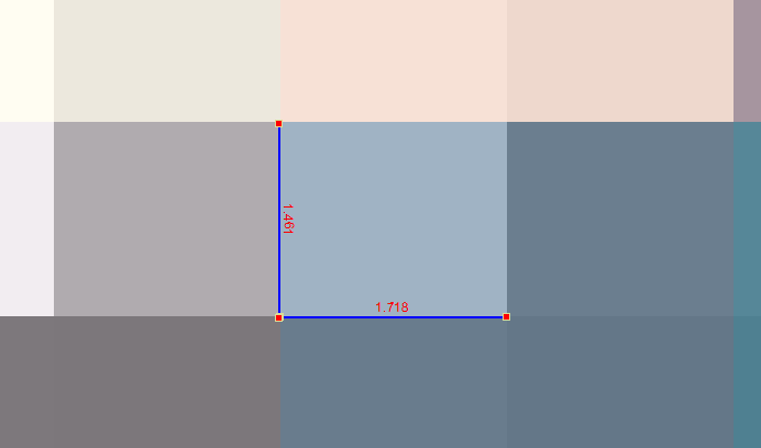
The raster graphic entity has several properties that are managed by DigFindR which include the overall size of the image in the X and Y plane, the transparency of the image, and the geographic area covered by the image. Most importantly, the squareness of the pixels in the image is controlled by DigFindR as well. To match aerial photography, which is basically a rectangle of pixels, to world coordinate space portrayed by the drawing/map, the dimensions of the raster in X and Y are usually required.
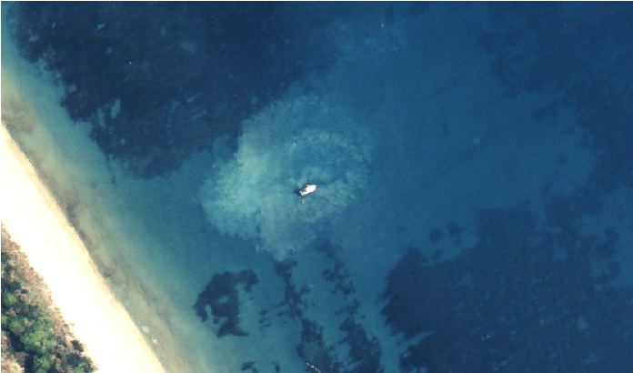
The three illustrations below are screen shots of a vessel digging near the Green Cabin from aerials furnished to sub-contractors by the Fishers in the early '90s. This aerial photography was collected for use in the dig maps on a day when the ocean was exceptionally clear. In the top-most illustration, the pixels can be measured as being 1.461 feet high by 1.718 feet wide. This ratio of height to width is called the "aspect ratio". The pixels are not square in this case. In the next illustration, the image is zoomed out some, but the pixels are still obvious and we can make out the image of a boat with her bow pointing to the northeast. In the bottom-most illustration the image is zoomed to a useful level where the pixels are no longer evident, but the image is clear to the point that we can make out dust particles and scratches on the film known in the trade as "blems" (blemishes).