Menu Bar
The Menu Bar hosts a series of drop-down menus providing the user with access to the many functions available in DigFindR. Some of the menu choices are augmented with convenient buttons on the Button Bar. There are a number of functions that must be used on occasion that are only available through menu selections.
The Menu Bar features the following groups of menu choices:
The FILE MENU
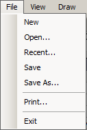
- New... open a new file for drawing. This file will be without any name until you save it with a name. While it is possible to save an empty drawing file with a name, this is generally not a good idea. If you open a drawing and don't add anything to it, do not save it.
- Open... open an existing file via the Open File Dialog. You can also use the
 button on the Button Bar.
- Recent... the Recent Files List will appear giving you a choice of files you have used previously. Their edit dates will appear and a preview of each is offered in a review pane. You can also use the
 button on the Button Bar.
- Save... use this selection to save a new drawing, or the one you previously loaded. If the current file is a previously existing file, it will be saved with its current filename automatically. You can use the Save function at any time, and you should do so with frequency if making many changes to your drawing thereby avoiding data loss should your system shut down or reboot unexpectedly. To perform this function, you can also use the
 button on the Button Bar.
- Save As... if you want to save the current drawing with a different filename, or in a different location on your drive, use this selection which summons the File Save Dialog. You can also use the
 button on the Button Bar to invoke this function.
 - Print... use this menu choice to activate the Print Dialog. This is a custom dialog which gives you a setup for the printer as well as a preview of the print output.
- Exit... use this menu choice to quit DigFindR. You will be asked to confirm your choice. You should always use this method of shutting down DigFindR to insure the program is terminated gracefully, and with special attention to the Log Sheet Dialog. While it is possible to kill DigFindR via the Control Box, that method does not give you the safety of a guaranteed data save prior to shut down.
The VIEW MENU
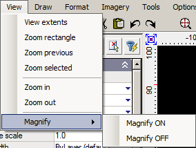
- Zoom Extents... use this menu choice to Zoom out completely in the Map Window to the full extent of all data in the current drawing file. You can also use the
 button on the Button Bar.
 - Zoom Window... if you want to Zoom to a particular extent in the Map Window, use this menu selection. You can also use the
 button on the Button Bar.
- Zoom Selected... this menu choice permits you to Zoom into the Map Window where an entity(s) is selected. This is particularly handy when using the 1715 Fleet maps, as some of them are quite busy, and it can be difficult to see details. You can also use the
 button on the Button Bar.
- Zoom Last... DigFindR remembers your Zoom sequences in order, so it is possible to Zoom to your previous view using this menu selection. You can also use the
 button on the Button Bar.
- Magnify View... this menu selection toggles the Magnify View window, a small window that magnifies objects beneath the cursor.
The DRAW MENU
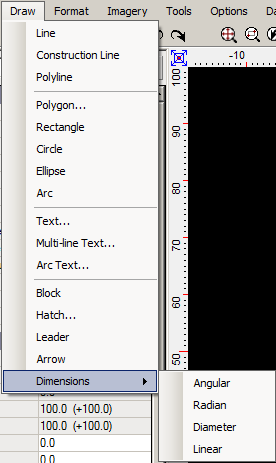
- Line... select this to begin drawing a line in the Map Window. Once you start, you can right click to continue in serial mode, or quit drawing lines. You can also use the Esc key to terminate drawing.
- Construction Line... this menu choice will permit you to draw a construction line. A construction line is a dashed line that has a given angle (determined by the user) running to infinity in both directions from the point of origin. Construction lines are extremely useful where absolute bearings need to be visible from great nadir distance, for example when you have zoomed far out from your map and wish to see a distant location in the Map Window. Because they have no bounds, it's easy to zoom out and select them for deletion. You do have the option of drawing a "ray" rather than a line by right clicking as you draw the construction line. A "ray" is a construction line with a single anchored end point.
- Polyline... use this selection to draw a polyline in the Map Window.
- Polygon... use this menu choice to draw a polygon. A polygon in this instance will be a closed polyline with a fixed number of sides. All sides will be of equal length. Be aware that you can also draw a polyline that closes on itself to produce a polygon, however, using this menu choice is the easiest way to construct polygons with fixed length sides that equal one another, such as squares and equilateral triangles.
- Rectangle... select this to construct a rectangle. Right click in the Map Window to choose the method required, or simply use the default by clicking on two extents.
- Circle... use this selection to begin drawing a circle in the Map Window. Circles may be drawn using radians, or points by right-clicking as you draw the circle. The default is by centerpoint and radian.
- Ellipse... click on this menu choice to begin drawing an ellipse. Right click in the Map Window to pick the method you wish to use.
- Arc... use this menu choice to draw arcs. As you begin drawing in the Map Window, right click to make a choice in your method of drawing the arc. Click on a start point, and an end point to begin the construction of the arc, then move the mouse away from the construct to add the arc line itself.
- Text... click on this menu choice to draw text that will occupy a single line. A dialog will appear where you type in the text string. Thereafter, you place the text in the Map Window, scale it, and rotate it to suit. The text dialog permits you to choose the style of the text and the point in the text string entity that will be used for alignment.
- Multiline Text... if you choose this menu selection you will first draw a rectangle on the screen which represents the bounding extents of your intended text content. Then a small window appears wherein you type the text you want to show in multiple lines. The "\P" string is reserved as a delimiter, meaning that you must insert it in the text you type into the window to break the text string into lines. This requires some practice. For example "this is a string\Pof text" would appear as...
this is a string
of text
- Arc Text... this menu choice will instantiate the arc text drawing. A dialog appears wherein you type the text and thereafter you use the cursor in the Map Window to place, scale, and rotate the text in its arc as affixed to a temporary circle symbol.
- Block... blocks are collections of entities that are selected into a single entity. Thereafter the block is saved in the drawing with a name, and can be "drawn" as a single entity. To "draw" a block entity, use this menu selection. Blocks can be scaled, copied, and rotated as if they were a single entity. You might have a block, for example that you use as a signature and description field for your drawings, or perhaps strings of text that you use repeatedly throughout your drawing/map.
- Hatch... hatch, or "pattern fill" may be defined by boundary and type. Once you have made this menu choice select a polygon to represent the boundary then select the hatch type from a dialog that automatically appears. In DigFindR, the standard AutoCAD hatch patterns are available from a file in the DigFindR home directory named "hatchs.pat". You can use other hatch patterns as desired, but you must associate the .pat file with the hatch dialog first. The existing hatchs.pat file will probably fill your needs.
- Leader... use this menu choice to draw text with a leading arrow line in the Map Window. A leader might be useful to add a particular label, but be advised the text and the leader itself can not be dis-associated from one another. Therefore, if you erase one, both are erased (deleted).
- Arrow... use this menu choice to drop an arrow shaped polygon into the Map Window. The arrow is of fixed proportions, but it can be useful to callout labels or other features in the Map Window.
- Dimensions... this menu choice will permit you to add dimensions to the Map Window. Generally you will not make use of the built-in dimensioning features found in the LiteCAD.DLL as they are designed for mechanical illustration rather than geographic illustration. There are four dimension styles available through a cascading menu.
The FORMAT MENU
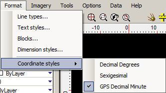
- Line types... use this menu choice to summon the LiteCAD Line Styles dialog.
- Text Styles... use this menu choice to summon the LiteCAD Text Styles dialog.
- Blocks... use this menu choice to summon the Block dialog. The Block dialog will list all the block entities in the drawing and it gives you the option of importing blocks from other drawings.
- Dimension Styles... use this menu choice to summon the LiteCAD Dimension Styles dialog.
- Coordinate styles... this menu choice opens a cascading menu giving you the choice of your coordinate readout seen in the Lat and Long display at the bottom of the program window. The default is the typical GPS notation of whole degree and decimal minute. On the fly you can change this to Decimal Degrees, or Sexigesimal (degree, minute, and decimal second).
The IMAGERY MENU
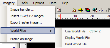
- Image Handler... use this menu choice to invoke the LiteCAD image dialog. This dialog permits you to assign graphic images to your current map file. Using the dialog, images can be added, delected and inserted into the Map Window.
- Insert ECW/JP2 Images... select this menu choice to add an Enhanced Compression Wavelet (ECW) image or a Joint Photo Expert Group 2000 (JP2) image to the Map Window. Unlike other raster images that are handled through the Image Handler facility, these two particular image types have their own world file placement coordinates built in. Subsequently, you do not have to place them in world space... they will automatically place themselves. Be aware that you must know in advance which coordinate system was used at the time the images were created.
- Export Raster Image... if you want to take a snapshot of the Map Window and save it as a raster graphic file, use this menu choice. A LiteCAD dialog will appear giving you a choice of resolution, directory storage, file type, and filename. This function is also available on the Button Bar through the
 button.
- World Files... this menu choice will cascade three additional menu choices.
- Use World File (Hot Key Combination Ctrl+F2)... if your image already has an associated World File, use this menu choice, or the dedicated Hot Key Combination to set the image into its proper coordinate space in the Map Window.
- Display World File... you can see the contents of a World File for any selected image in the Map Window by using this menu choice. If the image has no World File, a message will relay that information on the Map Window.
- Build World File... any selected image in the Map Window can have an associated World File built by using this menu choice. Once you have the image correctly sized and located in the Map Window use this function to build the World File, and thereafter that same image can be used in other drawing files covering similar ground by using the image World File.
- Frame an image... use this menu choice to place a border around any selected image. The path of the image file and its name will be added to the border at the top as a text string.
The TOOLS MENU
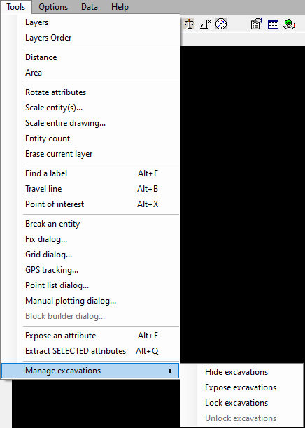
- Layers... use this menu choice to summon the LiteCAD Layers dialog. You can also use the
 button on the Button Bar for the same purpose.
- Layers Order... click on this menu choice to invoke the LiteCAD Layers Order display. This utility is used to move layers up or down in the layers display order, and to toggle the visibility of specific layers in the Map Window. You can also use the
 button on the Button Bar for the same purpose.
 - Distance... you can summon the distance measuring tool with this menu choice, or you may use the
 button on the Button Bar. Once the tool is invoked, right click on the Map Window to pop-up the distance measuring parameters.
- Area... this menu choice invokes the area measurement function in the Map Window. Once the tool is invoked, right click on the Map Window to pop-up the area measurement parameters. You must construct a polygon with a minimum of three sides to obtain an area measurement.
- Scale entity(s)... this menu choice will provide you with a dialog you can use to scale an entity to a desired size. You may also use the
 button on the Button Bar. It works with any entity that is selected, but only with a single entity. If more that one entity is selected, the last entity selected will be affected. The tool is primarily designed to scale graphic images, particularly aerials. Be aware that the Undo function does not work once the entity is scaled using this dialog. If you attempt to Undo the edit, the entity will be erased instead.
- Scale entire drawing...this menu choice is primarily furnished for scaling the original DWG format maps produced by AutoCAD. Those original drawings furnished by the 1715 Fleet lease holders are not suitable for use in DigFindR and must be scaled appropriately to take advantage of the multiple coordinate systems available in DigFindR. As a rule, you should avoid using this function on your source maps.
- Entity count... this menu choice will give you a quick count of the total number of entities in the current map/drawing.
- Erase current layer... use this menu choice to erase everything on the current working layer. The layer must not be locked. The
 button on the Button Bar performs this function as well. You might need to do this, if, for example, you are calculating positions using the Manual plotting dialog and need to refresh the Map Window for a new round of calculations. Be aware that this operation can not be Undone!
- Find a label... use this menu choice to invoke a tool that permits you to find and select text entities in the Map Window according to a search string you provide. The Hot Key Combination of Alt+F will also activate this function.
- Travel line... you can use this menu choice, or the Alt+B Hot Key Combination to use this function which interrogates any given selected line entity in the Map Window. The selected line will be annotated with its bearing, distance, and arrowheads indicating the direction of the line. A Travel Line can be used both as a north arrow and as a scale if necessary.
- Point of interest... while you can use this menu choice to operate the Point of Interest function, it's far more convenient to use the Alt+X Hot Key Combination. The function will place a cross measuring 40 feet wide at the current cursor location in the Map Window, and the latitude and longitude will be added to the symbol as text in the upper right quadrant of the cross symbol. Once the symbol and text are added to the Map Window, the view will zoom to that position.
- Break an entity... use this menu choice to instantiate a Break operation. Normally you might expect this to be found in the Edit Pop-Up menu, but it is an unusual tool. You can use it to fracture the lines of an entity if, for example, you want to erase part of a polyline, a segment of a single line, or a portion of a circle. Click on the menu choice and you will be presented with instructions to complete the operation.
- Fix dialog... use this menu choice or the
 button on the Button Bar to invoke the Fix Dialog. The Fix Dialog is used to establish a known position by latitude and longitude in the Map Window.
- Grid dialog... to use the Grid Dialog, click on this menu choice.
- GPS tracking... click on this menu choice to summon the GPS utility. You can also use the
 button on the Button Bar.
- Point list dialog... this menu choice will invoke the Point List Dialog. The Point List Dialog provides a means of adding symbols to the Map Window using delimited text files for labels and coordinate positions. Like its cousin the Data Utility, the Point List Dialog permits the user to GOTO positions of selected records as well as marking up those positions with symbols and labels. You can also activate the dialog by using the
 button on the Button Bar.
 - Manual plotting dialog... use this menu choice to invoke the Manual Plotting Dialog, or use the
 button on the Button Bar. The Manual Plotting Dialog uses any single selected line entity and rotates it in the Map Window to the desired bearing. Thereafter, the selected line is used as a Travel Line object and annotated accordingly. The Manual Plotting Dialog is most often used to reconstruct compass bearings. The Manual Plotting Dialog is a dual-purpose tool that also provides the functions necessary to determine fixes based on sextant bearings. The bearing calculations provide you with a means of computing decimal degree bearings from decimal minute, or sexigesimal notation.
- Expose an attribute... if you have an attribute selected, this function will display a small message box containing the attribute data. The message box provides you with an option to place the attribute data, as seen in the message box, next to the attribute symbol in the Map Window. This function is also available through the use of the Hot Key Combination of Alt+E, which is more practical. If you have more than one attribute selected, the last one in the selection set will be subject to this function, therefore, make it a practice to use this function with a single selected attribute.
- Extract SELECTED attributes... if interested in certain attributes (read digs) in the Map Window, you can select those of interest and use this menu choice to compile a CSV (Comma Save Value) text file that lists each selected attribute on its own line, with each data item separated by a comma. This extracted file is automatically named "Dump.CSV" and it is stored in DigFindR's home directory. The Dump.CSV file can be opened by the Point List Dialog and the records can be used to markup the Map Window.
- Manage excavations... opens a cascading sub-menu. The excavation management options make it easy to control the many attribute layers built into the traditional 1715 Fleet maps. Rather than unlocking, hiding, exposing, and/or locking each of the layers individually, they can be handled en mass using these menu choices.
- Hide excavations... use this menu choice to turn off the visibility of the layers in the 1715 Fleet maps that contain the excavation attributes.
- Expose excavations... use this menu choice to turn on the visibility of the layers in the 1715 Fleet maps that contain the excavation attributes.
- Lock excavations... use this menu choice to lock the layers in the 1715 Fleet maps that contain the excavation attributes.
- Unlock excavations... use this menu choice to unlock the layers in the 1715 Fleet maps that contain the excavation attributes.
The OPTIONS MENU
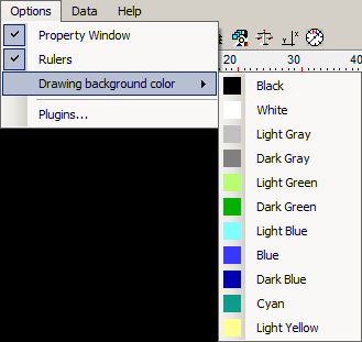
- Property Window... this menu choice is defaulted to a checked state, indicating that the Property Window is visible. Click on it to hide the Property Window. If not checked, click on it to expose the Property Window.
- Rulers... this menu choice is defaulted to a checked state, indicating that the Rulers are visible. Click on it to hide the Rulers. If not checked, click on it to expose the Rulers.
- Drawing background color... this menu choice exposes a cascading menu permitting you to select the background color of the Map Window. The default color is Black, but you may change it as desired by clicking on any of the colors in the cascading menu. Your selection may interfere with the visibility of entities, including attributes on visible layers.
- Plugins... use this menu choice to open the Plugins Dialog as needed.
The DATA MENU

Click on the Data menu choice to activate the Data Utility. You may also use the ![]() button on the Button Bar to activate the Data Utility. If the Data Utility has been minimized, clicking on the button or the menu will restore the Data Utility to view. Be aware that the Data Utility may take several seconds to load initially.
button on the Button Bar to activate the Data Utility. If the Data Utility has been minimized, clicking on the button or the menu will restore the Data Utility to view. Be aware that the Data Utility may take several seconds to load initially.
The HELP MENU
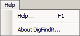
- Help... use this menu choice to open this Help File, or use the F1 Hot Key.
- About DigFindR... this menu choice will expose the About Box for the program. In the About Box, you will see the current compile date and copyright notices.