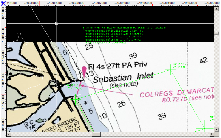
Map Window
The Map Window is the actual work space used to display and edit the excavation maps. DigFindR is a CAD (Computer Aided Drafting) program therefore, you can basically draw any 2D object you like in the Map Window, but for the sake of DigFindR's intended use, we only refer to this work space as the "Map Window".

As seen here, the Map Window can host graphic images such as raster maps, photos, and entities. Unlike raster graphics composed of pixels, the entities in CAD are not of fixed pixel size and represent precise mathematical points in space. Between these points are lines of various types that are visible at all times, regardless of the user's viewpoint. Some of the entities, such as text (which are nothing more than lines composed in symbolic forms) will obscure themselves at a predefined distance. CAD entities do not pixilate whereas raster graphics do pixilate as you zoom closer and closer to them. The illustration above is a pixilated raster image, not a true CAD work space... it is a snap shot of a CAD work space.
Data in the Map Window is controlled through several mechanisms, those being:
Entities can be placed in specific layers within the CAD drawing file, and those layers can be locked so that the entities on that layer can not be modified. The layers can be toggled as visible or invisible as the user requires.
Entities of specific types can be placed on specific layers as desired.
Entities can be of different colors, making them representative of certain qualities. This is the scheme used in the 1715 Fleet maps where excavation symbols are placed on specific layers, and the symbols themselves are of a given color. It is possible to turn off all the layers, or leave only certain ones visible while the rest are invisible. For example, there are many EH (Empty Hole) symbols in the maps, and it is useful on occasion to make the EH layer invisible in order to see what things have actually been recovered in certain areas.
The cursor is seen in the illustration above as a cross-hair with a small square in the middle. This indicates the cursor is in a state where it can be used to select a given entity with a click of the mouse left button. Otherwise, if the small square is not visible, the cursor is not in the active edit mode and it can not be used to select entities.