Layers
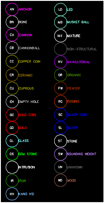
One of the mainstays in CAD is the idea of isolating entities on various layers, and this is certainly the case with the original 1715 Fleet maps built using AutoCAD. The layer strategy is fundamental to the overall utility of the maps. In these maps, the items recovered by salvors are symbolized by their type, with all of the objects of a specific type located on a specific layer. And each of those layers is assigned a color. Using this strategy, a Key can be constructed that features both a color and a text moniker for each symbol on the layer. For example, "SC" stands for "silver coin" and all the symbols on the SC layer are blue. In the original maps the symbols themselves are circles representing the area, about 22 feet in diameter, where an item was recovered. The center of the circle should indicate the fix in latitude and longitude where the excavation occurred.
When the mapping project first began, the output from the maps was entirely paper-based. The maps were plotted on large format plotters with a limited number of inks to choose from. Meanwhile, it is now possible to display many more colors, and salvors now have computer systems of their own that can use the map files directly without relying on paper versions; that was not the case originally.
The Key for a 1715 Fleet map of 2016 is seen below. Note the 2 character monikers and the various colors. There are sixteen colors in the original maps, but there are 29 object categories. Subsequently, there are 29 unique layers in the drawing set aside for the artifacts. There are many more layers set aside for other elements of the drawing/map which include photo layers, shoreline layer, and positional grid layers as well. In most of the 1715 Fleet maps, there are usually around 50 separate layers, therefore, understanding how layers work is important to managing the maps in the DigFindR program.
The primary means of control through the use of the layering system is found through visibility and locking.
- Layers can be "turned off" and "turned on". When turned off, they will not be visible in the Map Window... the layer is still there, it simply is not displayed. When the layer is not visible, entities on that layer can not be selected.
- Layers can be "locked" or "unlocked". In the locked state, entities in the layer can not be selected and therefore can not be edited or deleted. So a layer can be visible, but even though you can see it in the Map Window, entities on that layer are not selectable if the layer is locked.
- You can add Layers to the drawing, and you can delete layers from the drawing. You can not delete a layer that has entities in it without first selecting all the entities in that layer and deleting them first.
- All drawings have a layer named "layer 0". Never delete layer 0 or the file will become corrupted.
- You can only construct entities on one layer at a time, and that is your "active" layer. There can only be one layer active at any time. Avoid making the active layer invisible.
Layer Dialog
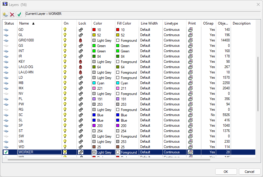
The Layers Dialog used to control the layers can be summoned from the Tools menu in the Menu Bar, or by clicking on the  button in the Button Bar. The dialog is sizable... you can grab any corner of it by by holding down the left mouse button when you see the diagonal double-headed arrow as you hover near the corners of the dialog boundary, and move the mouse to resize the dialog window. In the example image below, one of the 1715 Fleet maps is loaded and the Layer Dialog has focus. In the Title Bar of the dialog you see there are 56 layers in the drawing. The current layer with focus is the active layer, in this case the layer is named "WORKER" and a green check mark signifies this to be the active layer. The light bulb symbol is yellow, indicating the active layer to be visible (as are all the layers seen inside the dialog in this example). The symbol in the Lock column is "unlocked", indicating that entities in the WORKER layer can be selected. The same holds true for the first two layers seen as GD, and GL. Be aware that you are only seeing some of the layers in the dialog, and you have to scroll the list, or expand the dialog's size to see more of them.
The WORKER layer's color is "Light Grey". The fill color for all closed figures, if you fill them is also "Foreground" color, or white. The line width for all entities on the WORKER layer will be the default (one pixel). The linetype will be "Continuous (solid)", the layer can be printed as the printer symbol is visible in the Print column, the layer can be managed using the Object Snapping utility as the Osnap column indicates "Yes" and the number of entities in the collar layer is 28.
Notice that some of the layer symbols in the extreme left of the dialog are grayed out, indicating that there is nothing in that layer. For example the layer SW has nothing in it.
To make any layer the active layer, simply click on its layer symbol in the Status column. Likewise to toggle visibility and lock state, click on the light bulb symbol and lock symbol. Be aware that you can turn all layers on or off by clicking on one layer's light bulb, and then holding down your Shift key while clicking on the last layer's light bulb symbol that you want to change. The same goes for the lock symbol as well. With so many layers involved, you might need to do this occasionally.
You can change the name of a layer by double-clicking on its name in the Name column. Do NOT change the names of layers in the original map files, and do not rename layer 0! If you request support for the use of these files, I must assume that your drawing matches my own by way of layer name, and I must assume you've left layer 0 intact. Otherwise, you can add as many layers to the drawings as you like and you can name them anything you like, so long as the names do not conflict with existing layer names.
When you click on colors in the Color and Fill Color columns, a Windows Dialog will appear giving you the opportunity to change the colors. As a rule you should never change the colors provided in the original source maps provided to you by the authority which gave them to you. The Key to the drawings hinges upon colors, and you need to maintain the authenticity of the product you are using if you intend to share data on paper or through digital means.
The last column in the Layer Dialog is "Description". Generally nothing is found in this layer, but you can put your own comment in there as desired. If you don't know what the moniker "SC" means, for instance, you could put "Silver Coins" in the Description column.
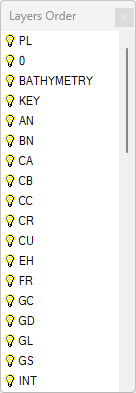
Layers Order Tool
There is an additional tool you can use to manage two specific attributes of the layers and this one is designed specifically to move layers throughout the stack. The tool is found in the Tools menu in the Menu Bar, as the "Layers Order" menu selection; you can also activate it by using the  button on the Button Bar. Once again, this brief dialog window is sizable like its cousin the Layer Dialog. It's a simple matter to turn on or off the layers using this tool, and to move layers up or down in the stack, by clicking on the layer name, holding down the left mouse button and moving the mouse. Let go of the button and the layer will assume its new position in the layers' order. You might want to do this if you've added a raster graphic to the drawing, and you want it to be bottom-most in the Map Window, so that all the entities drawn in the upper layers are visible.