Fixed Position Grids
Fixed Position Grids are grids that are based on fixed points of reference in the Map Window, according to the geographic coordinate system in use. Normally while using the 1715 Fleet maps this will be a Latitude and Longitude expressed in decimal minute format. Once a Fixed Position Grid is constructed, it can NOT be moved, otherwise its labels will no longer have any meaning.
To construct a Fixed Position Grid open the Grid Dialog via the TOOLS MENU as seen below.
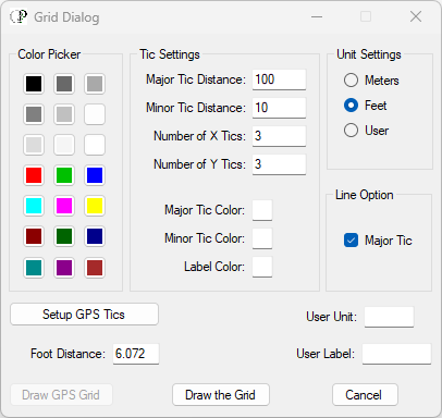
Note the Foot Distance is defaulted to a value of 6.072 feet. This represents the distance of one thousandth of a decimal minute in the latitudes of the 1715 Fleet wrecks. This value changes as you move north or south of the Equator. For 1715 Fleet maps, leave the default value of 6.072 feet in place. Every time you move 6.072 feet in perpendicular distance north, south, east, or west you change the value of the third digit behind the decimal minute value reading in your Map Window as well as on your GPS readout. The two figures should jive with one another.
For example, let's say you are at a position of 27° 45.409' N. and 80° 23.433' W. If you move 6.072 feet dead north of that position, your GPS should read as 27° 45.410' N. and 80° 23.433' W.
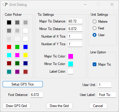
To setup your Fixed Position Grid, set your colors for Major Tic, Minor Tic, and Label. If you intend to print the grid on paper, you need to limit the size of the grid so that it will print well, with all the labels readable on the paper output, therefore I recommend that you limit the grid's extents to 60.72 feet, which is a tenfold increment of the 6.072 measurement. If you open the Grid Dialog and click on the button labeled "Setup GPS Tics", those values are the default. An example is shown below.
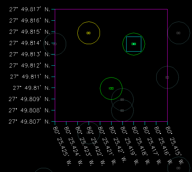
* It's good practice, when using the DigFindR maps furnished by Signum Ops, to use grid snapping mode when setting up a GPS grid. The Signum Ops maps are metered using minor tics with a value of 6.072 feet per X and Y. If you do this, the metrics will always be in three decimal place minute readouts as seen below, matching your GPS receiver readout.
I've also selected magenta as the Major Tic Color, teal as the Minor Tic Color, and white as the Label Color. At this point you can focus on the Map Window with your cursor and move to the position where you want the lower left corner of the grid to originate. RIGHT CLICK to drop the cursor. Ignore any pop-up menus. Click on the button labeled "Draw GPS Grid". Within a few seconds the grid will be drawn. You may have to zoom out to see all of it.
In the sample illustration below, I've created a Fixed Position Grid in an area where I've recently excavated, but I've decided that more digging is required. Using this grid on paper, I can navigate to any position inside the grid using my GPS, with confidence that I will be positioning myself appropriately.
To print this image, use the Print Dialog found on the FILE MENU in the Menu Bar. It will appear as seen below.
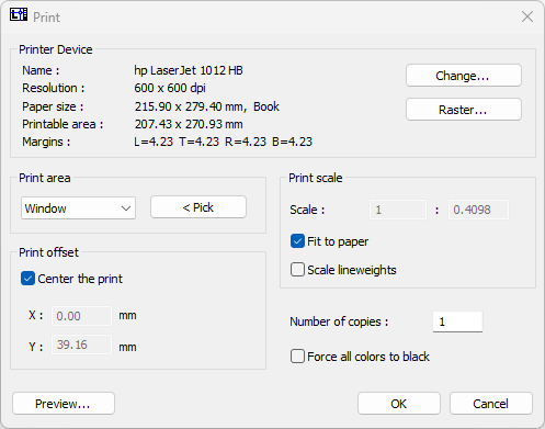
Use the Print area option of "Window", and click on the button labeled "<Pick". The dialog will disappear giving you the opportunity to draw a rectangle around the image in the Map Window that you want to print. As soon as you've done that, the dialog will reappear. Click on the button labeled "Preview..." and you will see something like this image below.
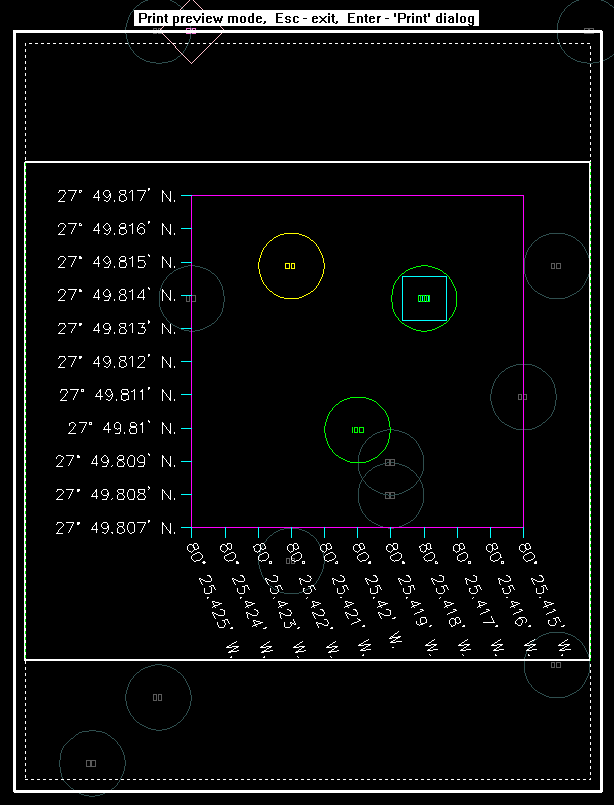
Strike your Enter key on the keyboard and the the Print Dialog will reappear. Use it to print the image. Be aware that the blue bordered area is the image you selected with the Pick Window function, and the red bordered area represents the extents of your currently selected printer page size (usually 8.5 X 11 inches as seen in this example). You may have to drive out a print job several times to get the desired results. If you're using a laser printer that only prints grayscale, you should indicate that all colors should be printed as black. If you are using a color printer, it may print all the white characters as black. This all depends upon the equipment you use.
While you may not be able to read all the text in your computer's display, your printer will render the characters properly.