Coordinate Grid Snap
There is an underlying grid built into DigFindR that is not visible by default. If your horizontal view extent in the Map Window is 300 feet wide or less, you can see the grid if you turn it on. To toggle Grid view, use your F7 function key on the keyboard, or right click in the Map Window and summon the assisting menu that looks like this:
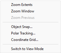
Select "Coordinate Grid..."
The LiteCAD pop-up dialog for Coordinate Grid will appear:
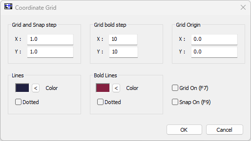
The default Grid step is 1 foot with a bold step of 10 feet. As you zoom in the grid will populate according to the view extent of the Map Window. When your extent is 50 feet or less, the grid will display in 1 foot increments.
With the Grid visible you can draw entities and your cursor will be drawn to the grid provided you have a special snap mode toggled on. You can use the F9 function key on the keyboard to activate Grid snapping mode. Be aware that Grid snapping can be activated regardless of Grid visibility. Generally you will not need to use Grid snap, but it does come in handy for drawing closed polygon figures that can subsequently be filled with solid colors or hatch.
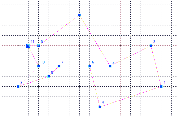
The example shown below features a selected polyline drawn using Grid snap. Each vertex falls directly on a grid corner. Therefore, in this figure, the distance between vertex 6 and vertex 7 is exactly 3 feet and the horizontal distance between vertex 3 and vertex 4 is 1 foot. The vertical distance between vertex 3 and vertex 4 is 4 feet.