Sextant Positions
Prior to the advent of commercial Geographic Positioning System receivers, excavation data for the 1715 Fleet operations were recorded using sextants. An array of markers were set at the dune, each having a number or letter. The salvors would take measurements of angles between these markers and those fixes were used to plot their position on a chart. The majority of excavation symbols found in the Fleet excavation maps were recorded in this fashion. After 2000, GPS replaced the sextant positioning routine, and greater accuracy was subsequently achieved when recording excavation position. Normally, the GPS receiver's antennae is located at the stern of the salvage vessel, in the proximity of the vessel's blowers, providing a location with an offset of several feet, which is negligible.
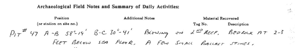
Below is a Field Note sample of the vessel Tequesta from back in 1990 while she worked at the Cannon Wreck site. Note the fixes taken between Markers A-B, and Markers B-C. The angle between Markers A-B is 58 degrees and 19 minutes while the angle between Markers B-C is 30 degrees and 41 minutes.
Marker Layer
In the digital Fleet excavation maps you will find a layer named "1_MARKERS", which contains the locations of the markers erected specifically for sextant bearings. Each is labeled by an alphabetic character, or a numeral. Be aware that, depending upon which "wreck" you are working on, the alphabetic ID of a given marker is not unique, to wit: there is an A marker at the Cabin Wreck location and there is an A marker at the Cannon Wreck location as well, therefore, you must have some idea of which area you are working on before you can construct positions using sextant markers.
The markers are enumerated from north to south, USUALLY, but NOT ALWAYS. At the Cabin Wreck for example, you find markers A, B, and C enumerated from south to north, as is the case at the Cannon Wreck.
As you will be working EAST of the shoreline, you need to measure distances between markers from north to south and compute the slope angle between the markers from north to south. The compass bearing between markers is measured from the northern marker to the southern marker, basically adhering to the compass or watch-face, both running in a clock-wise direction. To wit: if you were constructing sextant fixes on the west coast of Florida, you would be facing to the west, and would measure slope angles between markers from south to north.
Order of Operation
Using the above sample record for the Cannon Wreck you would...
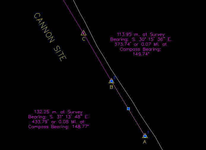
- Draw a line between marker C and B, and draw another between B and A. (try using a serial line in this instance to make sure the lines meet end to end for greater accuracy). ALWAYS DRAW FROM NORTH TO SOUTH WHEN CONSTRUCTING THESE BASE LINES. Otherwise, the functions used to find the sextant position will not work, or they might be in reverse!
- Select each line separately and use the Travel Line function to annotate each line. This will give you the distance between each marker, and the slope angle as seen below. In the illustration, the text which is usually displayed in two lines along the Travel Line itself, are seen rotated and compressed for the sake of clarity.
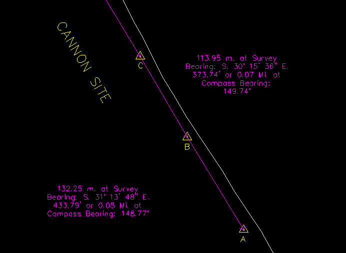
You've now established the slope between C and B as a decimal degree reading of 149.74 degrees, and the slope between B and A as a decimal degree reading of 148.77 degrees. The distance between C and B is 773.74 feet, and the distance between B and A is 433.79 feet.
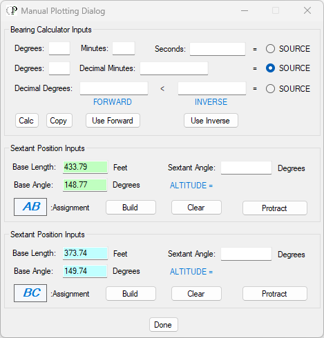
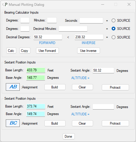
- Open the Manual Plotting Dialog and fill out the information collected in the panels for the two sextant bearings. NOTE: the "Assignment" text boxes are furnished for your convenience. They are not automatically populated, you have to put the characters in yourself from the keyboard. Since you will probably be doing a number of bearings between the same two sets of markers, the Assignment labels help you keep track of what you are doing.
- Now you need to furnish the decimal degree sextant angle for the A-B bearing. According to the record, the sextant bearing for A-B is 58 degrees and 19 whole minutes so you can input the degree and whole minute in the middle source (Degrees and Decimal Minutes), OR, you can use the topmost source and input the degree, the minute, and then add a 0 to the seconds field, and use that for the source if you like. Once you've supplied the inputs, click on the "Calc" button and the decimal degree sextant angle will appear in the Decimal Degrees FORWARD text box. That is the one you need, not the INVERSE value.
- Double-click on the Sextant Angle textbox for Assignment A-B, and the Decimal Degree value from the Bearing Calculator will populate the textbox. You are now ready to setup the A-B bearing circle in the Map Window. The Manual Plotting Dialog will now appear as seen below where the source chosen was the Decimal Minutes format:
- At this point you need to select the line running from Marker A to Marker B in the Map Window and place the cursor/Pick Box on the middle handle of the line. Now right-click to drop the cursor at that position. This is very important, because the construction of the sextant bearing circle will be built from that exact point. A popup menu will appear; ignore it and click anywhere outside of the Map Window or on the Manual Plotting Dialog form. The Map Window will now appear as seen below:
- Click on the "Build" button for Assignment A-B. The construct for the A-B sextant bearing will be drawn in the Map Window. An Altitude value of 133 FEET will appear in the Manual Plotting Dialog's Assignment A-B panel and the construct will appear as seen below:
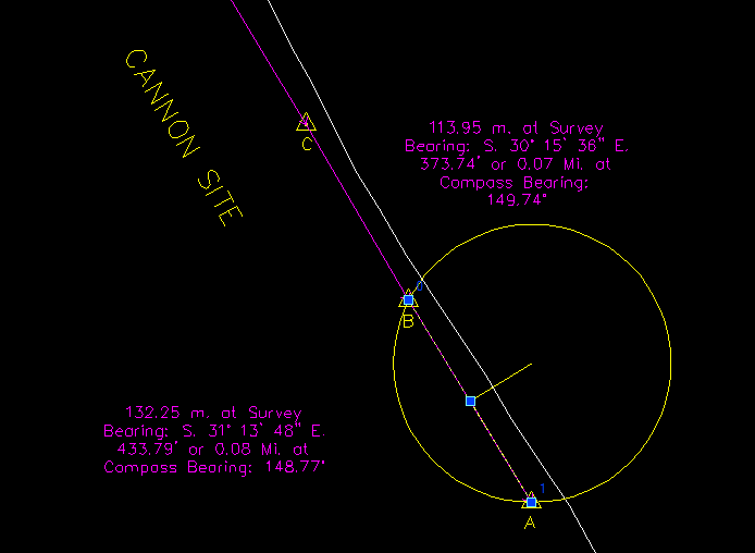
The Altitude line is drawn perpendicular to the base line for a computed distance based upon the length of the base line and the sextant bearing angle. The open end of the Altitude line is used to construct a circle that has radians to both Marker A and Marker B. So you've constructed a Pythagorean triangle using the radian value as the long side of the triangle (it is not drawn, simply inferred in the drawing itself). The base line is actually now a chord of the circle.
- Repeat the procedure for Assignment B-C and you will construct a second circle as seen below:
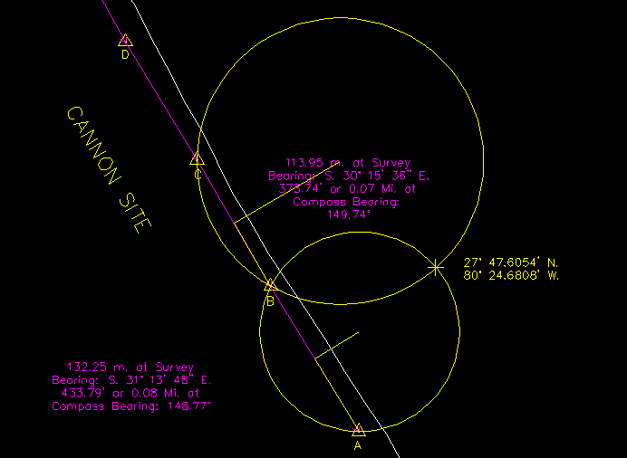
The point where the two circles intersect is the actual location where the two sextant bearings were obtained, in this case 27 47.6054 degrees north and 80 24.6808 degrees west.
- If you wish to use a new set of markers, click on the "Clear" button in both Assignment panels to empty the textboxes.