Set Bearing Lines
The Bearing Calculator is used to set lines on specific angles, just as if you had drawn them using a protractor and compass on a paper chart. You can access the Bearing Calculator by selecting it in in the TOOLS MENU or by clicking on the  button in the Button Bar. The Bearing Calculator looks like this when activated:
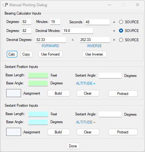
By default, the dialog is set to use decimal minute notation as the source of the bearing's direction. You can use sexigesimal (degrees, minutes, seconds) or decimal degrees as well. This default was set intentionally so that the Bearing Calculator function would support written sextant bearing records. If you are using a compass to take a sighting, then you will probably want to use decimal degrees as a source. In every case, no matter the notation style used for source, the angle computations are resolved to decimal degrees, therefore, as sexigesimal is not a number system fixed on a base of 10, there will be some deviations. Decimal degrees is the preferred choice.
Simply click on the radio button for Source to indicate the notation you are using. Then click on the "Calc" button, and the equivalent values for all three notation styles will appear as seen above.
Once you have a bearing calculated, you can pass that value on to a selected line entity in the Map Window by clicking on the "Use Forward" button or the "Use Inverse" button. When you do this, the selected line will be handled with the "Travel Line" function found in the TOOLS MENU, with the exception that the bearing will be passed on to the function, rather than simply having the function determine the given line's angle as it exists. If, for example, you used the Bearing Calculator to set a selected line entity using the "Use Forward" button, the result would be as seen below:
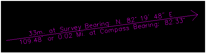
Note the Survey Bearing is provided which will have no value to you unless you have data, such as a boundary traverse expressed in a legal property description. This might be the case if you were laying out a new lease and you wished to submit a traverse to the state in your application. Otherwise, the Compass Bearing will be the value used. Also, note the arrow head which is pointing in the direction of the bearing as would be duplicated on a compass card. The Travel Line function also notes the length of the selected line entity in equivalent meters, foot distance, and miles.
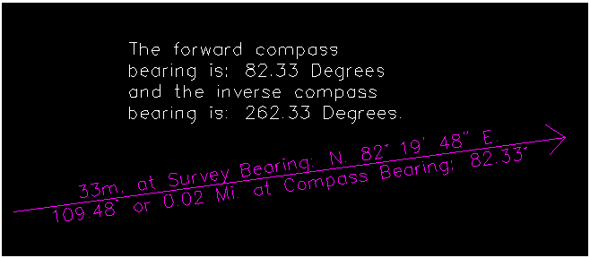
An additional feature of the Bearing Calculator is found in the "Copy" button. Once bearings are calculated you can copy a descriptive string into the Windows Clipboard that can be added to the Map Window using the Multi Line text entity as illustrated below:
You now have a line with a fixed bearing in place. Using this line as a bench mark, you can lay out a Construction Line that you can move into position in the Map Window with that exact bearing. To do this;
- Select the line you just set using the Bearing Calculator
- Draw a Construction Line by anchoring it to the handles on the selected line... this will duplicate the angle for the Construction Line
- Un-select everything
- Select the Construction Line and move it to its relevant position in the Map Window
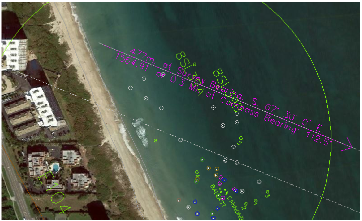
This maneuver is illustrated below where the Construction Line is eventually set against the corner of a building. Using this method from a boat, you might take a bearing on two building corners, plot them using this method, and where the two construction lines cross, you would have your position. This is not necessary these days as we have our GPS to give us a position in real time, but if you find old records that give bearings from sea, and the monuments used for sightings are still in place, you can use this method to determine where the vessel was located (for example while making recoveries, sans beach markers and prior to GPS).